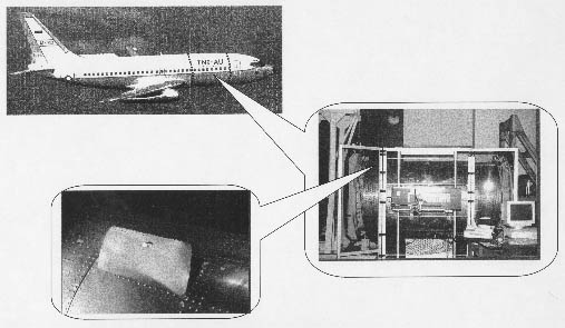

The express analysis was also used for crack initiation prediction, when it is planned to apply synchronized combination of pressure and bending load to the second barrel specimen. The general results of the express analysis for both cases of load, are summarized in Table 1.
Table 1. Express analysis general results
|
|
|
|
|
|||
|
|
|
|
|
|
||
|
|
|
|
|
|
|
|
|
|
|
|
||||
|
(pressure+bending) |
|
|
|
|
|
|
|
|
|
|
||||
|
(pressure+bending) |
|
|
|
|
|
|
|
|
|
|
||||
|
(pressure+bending) |
|
|
|
|
|
|
|
|
|
|
||||
Then contact problem for a pin loaded hole of an ordinary fastener from the outer row was solved. Tangential stress curves along hole edge are given in Figure.
This stress component is supposed to be fatigue-critical in the case that the interference fit can�t be guaranteed. Then crack initiation life was calculated (see results in Table 2) using the algorithm described earlier. The material parameters used were those for D16-AT aluminum alloy material that is considered as an analogue one to 2024-T3 alloy.
|
|
|
|
|
|
|
|
||
|
|
|
|
|
|
|
|
|
|
|
|
|
|
|
|
|
|
|
|
More accurate geometrically nonlinear FE analysis, as well as sub-modeling procedure, were implemented using an ANSYS54 code. The nonlinear analysis provided better correlation between numerical and experimental results than the linear analysis achieved with. Sub-modeling procedure, also known as cut-boundary displacement method or the specified boundary displacement method, ensures the maximum accuracy for boundary condition transfer available for a given FEA code. The Swift formula was exploited again to get rivet flexibility/stiffness for the lap joint model.
|
|
|
|
|
|
|
|
||
|
|
|
|
|
Back to "An approach for prediction..."